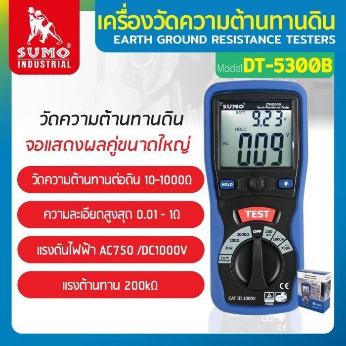
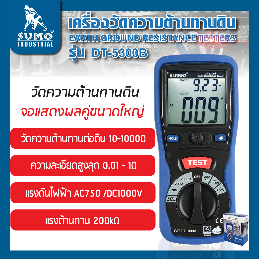
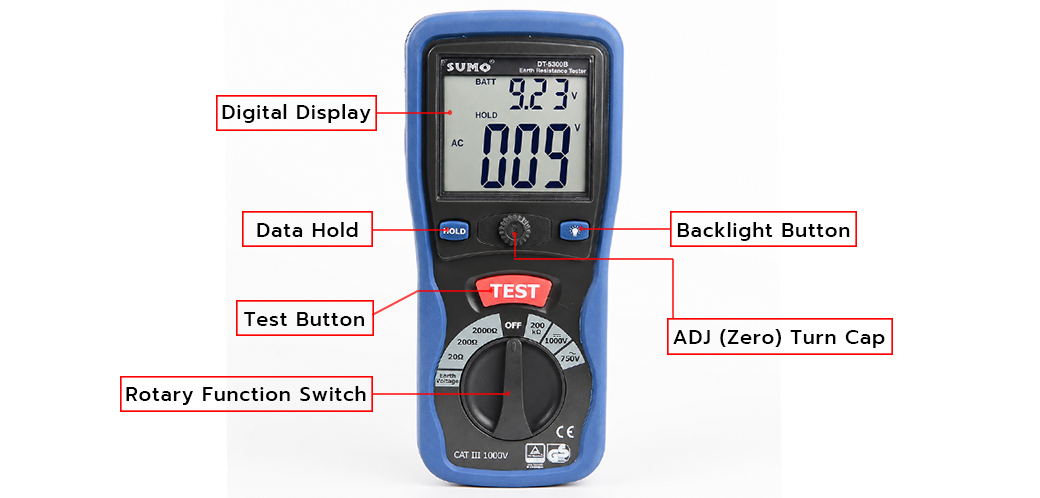
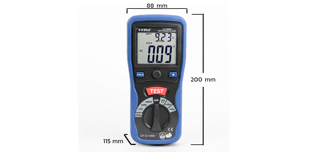
Electronic Digital Earth Resistance Tester is direct replacement of the conventional hand generator type tester. It is designed for measurement of the resistance of earthing used in the electrical equipment as well as for measurement of ground resistivity. It can used for measurements of the other low regular and liquid resistance. It can also be used for measurement of voltage AC, voltage DC and resistance. The instrument has wide application for testing earthing installation in power based industries, telecommunication networks and electrical traction systems etc.
This Earth Resistance Tester is designed to measure earth resistance and evaluate soil conditions, helping users design and install an effective grounding system.
Before measuring Ground Resistance, always measure Earth Voltage first to check for any voltage present in the ground and ensure safe operation.
Measuring Earth Voltage
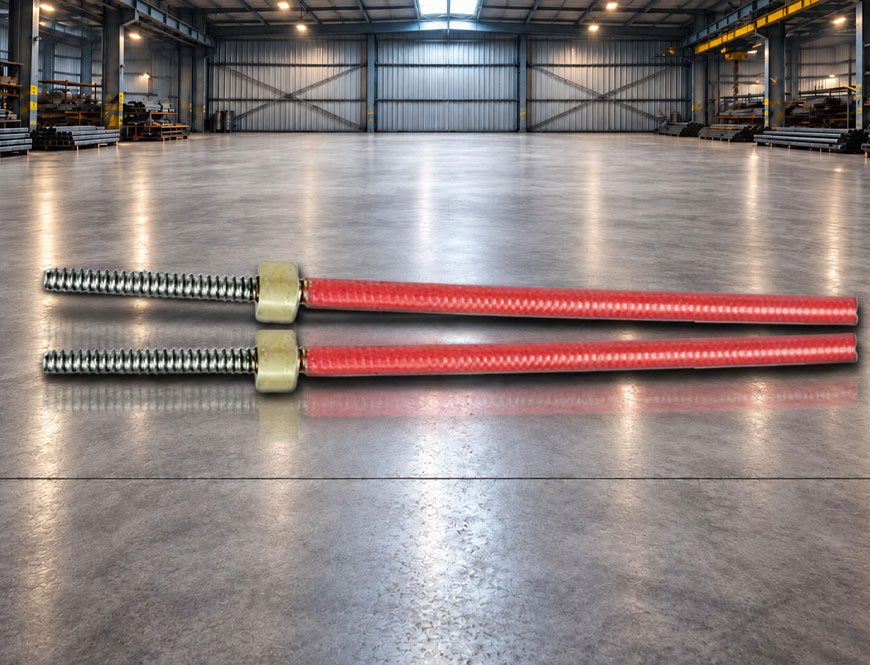
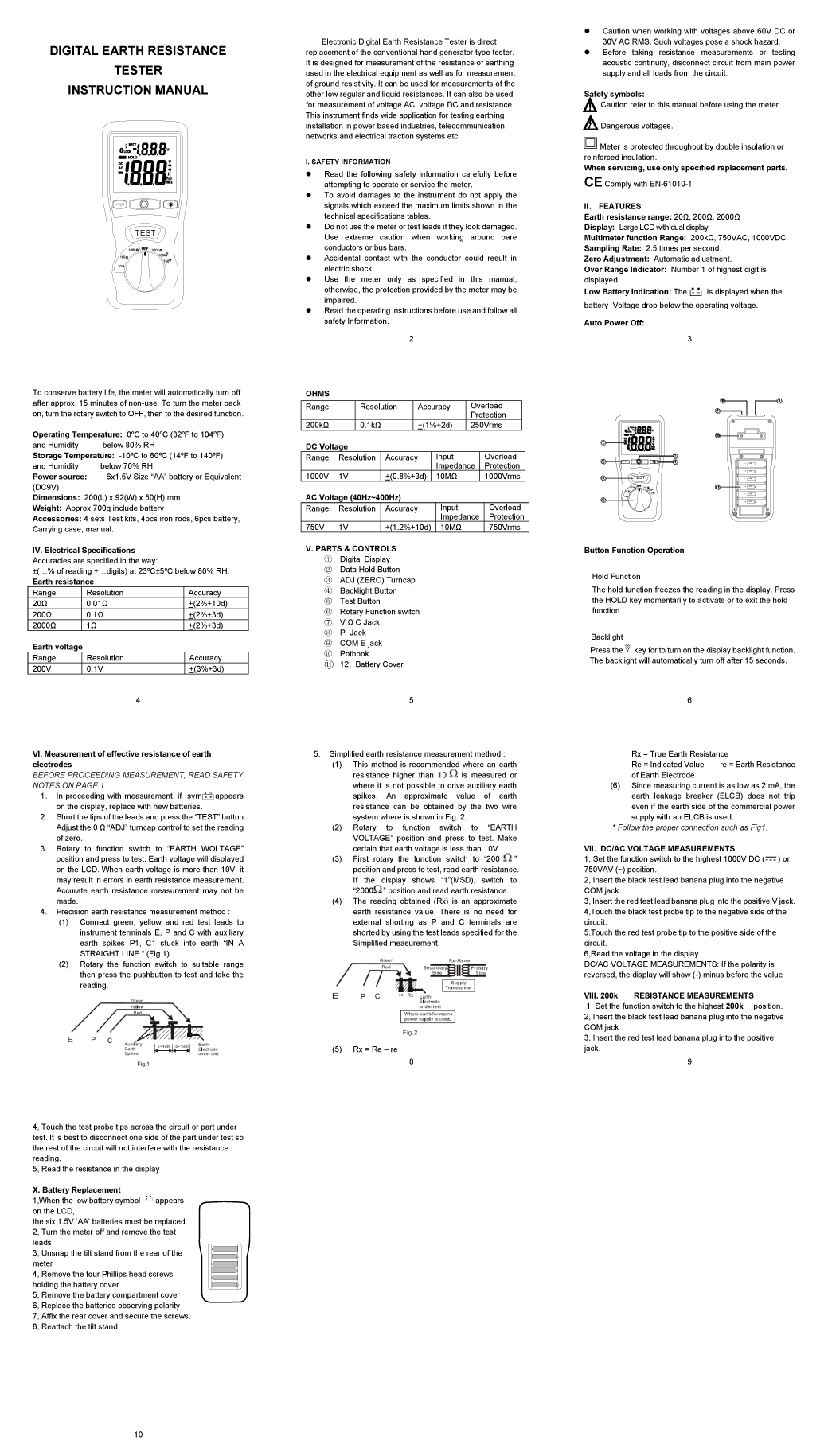
Install the three test rods. Place the red rod at the farthest point, connect the green rod to the grounding electrode, and install the yellow rod midway between the red and green rods.
The recommended distance between the green rod and the red rod is 10–20 meters. A greater distance generally provides more accurate measurement results.
Connect the test leads to the corresponding color-coded terminals on the tester.
Before taking measurements, check the resistance of the test leads. Set the rotary switch to the 20Ω range and short the test lead clips together. Press TEST. If the display does not read 0Ω, adjust the zero-adjust knob until 0Ω is displayed. Then connect the test leads to the corresponding test rods.
Set the rotary switch to the Earth Voltage range and perform the measurement. If the measured voltage exceeds 10V, identify and eliminate the cause before measuring Ground Resistance.
Measuring Ground Resistance
Always measure Earth Voltage before measuring Ground Resistance to ensure the safety of both the user and the instrument.
Perform the ground resistance measurement three times to verify the accuracy of the result.
First, set the rotary switch to the 200Ω range to check the approximate resistance value. If the measured value is below 20Ω, switch to the 20Ω range for higher measurement resolution.
First measurement : Press TEST and record the displayed value.
Second and third measurements : Move the yellow test rod 1 meter forward and 1 meter backward from its original position, then press TEST to take each measurement.
Calculate the final ground resistance using the three measured values.
For residential grounding systems, a measured resistance of 5Ω or less is considered acceptable. If the measured value is greater than 10Ω, the grounding system may no longer provide adequate performance and should be inspected or improved.
การเปลี่ยนแบตเตอรี่ใหม่ (Battery Replacement)
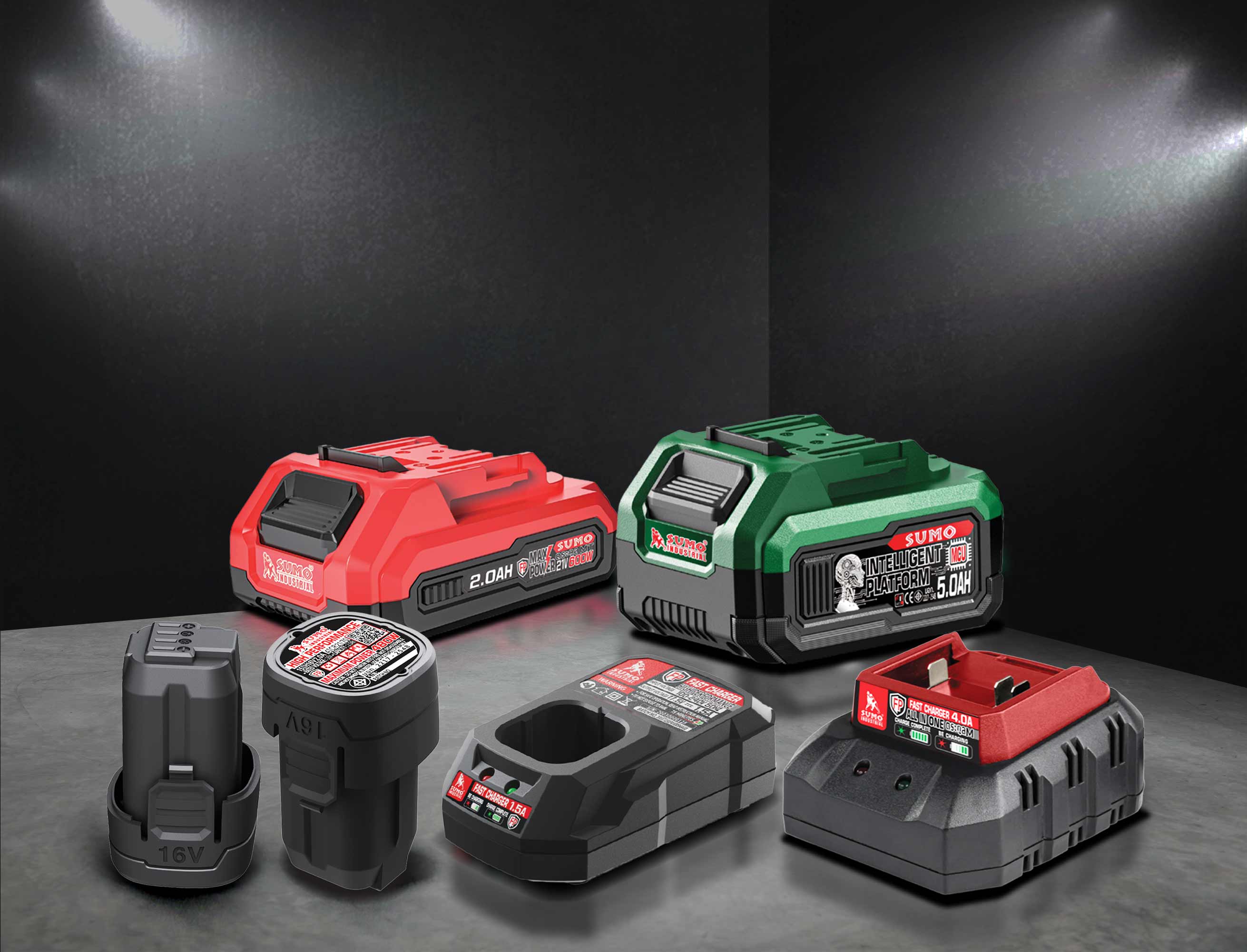
เมื่อแบตเตอรี่ต่ำจะมีสัญลักษณ์ตัวอย่างปรากฏขึ้นบนหน้าจ ต้องเปลี่ยนแบตเตอรี่ AA 1.5 V จำนวน 6 ก้อนแทนที่แบตเตอรี่เก่า


 1.เจียร ตัด ขัด ถู
 2.งานเชื่อม ตัดพลาสม่า
  3.อุปกรณ์เพื่อความปลอดภัย
  4.เจาะ เซาะ กัด เลื่อย
  5.เครื่องมือวัด
  6.อุปกรณ์ไฟฟ้า
  7.อุปกรณ์ลม
  8.เครื่องมือไฟฟ้า
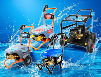
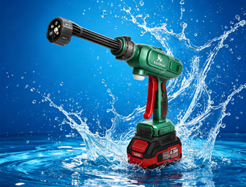
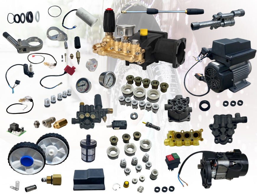
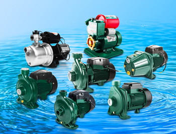
  9.ปั๊มน้ำ เครื่องอัดฉีด
  10.อุปกรณ์ดูแลรถยนต์
  11.เคมีภัณฑ์
  12.เครื่องมือ
  13.เครื่องจักร